Яндекс

Sunday, November 17, 2019

Rendering in Low Level Emulation mode. Part III

Hi!

In the previous article I described a new approach to processing N64 low-level polygons. This approach helped me to solve several serious issues with LLE rendering in general. However, main practical benefit was expected in Golden Eye, Perfect Dark and Killer Instinct Gold - the only games, which can't work properly without LLE support. Does the new method help to fix LLE-related issues in these games? Unfortunately, no. For example, KI with old method looks like this:
It looks nearly the same with the new method.

So, the problem is somewhere else. The source of the problem was discovered quite quickly. The sky on the screen-shot above has rendered by one low-level triangle command. As I explained before, low-level triangle commands render not triangles but trapezoids. In this case one triangle command renders the sky rectangle. I noticed that lower vertices of the rectangle have negative W coordinate. Normally, W can not be negative. Polygon with negative W vertex coordinate must be clipped. The microcode running on RSP performs the clipping. However, sky polygons in KI, sky and water polygons in GE and PD are exceptions. Crafty Rare programmers sent raw low-level polygons data directly to RDP bypassing RSP processing. That is why these games need LLE support even in HLE mode. Probably the code, which generates this low-level data is buggy and sometimes produces incorrect result. You may run KI and see that sometimes the sky is correct and few seconds later it is wrong again.

AL RDP plugin has no problems with such polygons. After long debugging I found that it implements an interesting feature: texture coordinates clamp. It is not the standard tile clamp explained in N64 manuals. It is rather a sanity test: if texture coordinate can't be calculated correctly it force clamped to some special value. Negative W is one of the cases, which triggers that clamping. I dumped texture coordinates calculated by AL RDP for KI case. Look at this diagram:
It shows how S coordinate changes from top to bottom of the rectangle. It wraps several times, but at the bottom becomes constant. It is where W coordinate turns negative. The sky polygon alone looks like this (click to see full size):
As you may see, the very bottom part of the polygon is filled with some constant color. This part usually is covered by other geometry, but I hacked the AL RDP sources to get that picture.

AL RDP software plugin emulates work of RDP and renders that polygon line by line. When W becomes negative at some line, RDP clamps texture coordinate to some constant. That constant coordinate points to some texel inside the texture, and this texel is used for all pixels in the line.

Hardware render can't work this way. Color, depth and texture coordinates provided per vertex and interpolated for each pixel inside the polygon. Interpolation is a smooth function. In this case texture coordinates do not behave smoothly and interpolation does not work as it should.

I found a solution. All coordinates work properly while W is positive. If W becomes negative for some vertex (or vertices), the algorithm searches for the Y coordinate, where W changes its sign. Then part of the polygon from the top to that Y is rendered. The part below Y rendered too, but all vertices of that part have the same texture coordinate, so it is filled with some constant color fetched from the texture. The result:

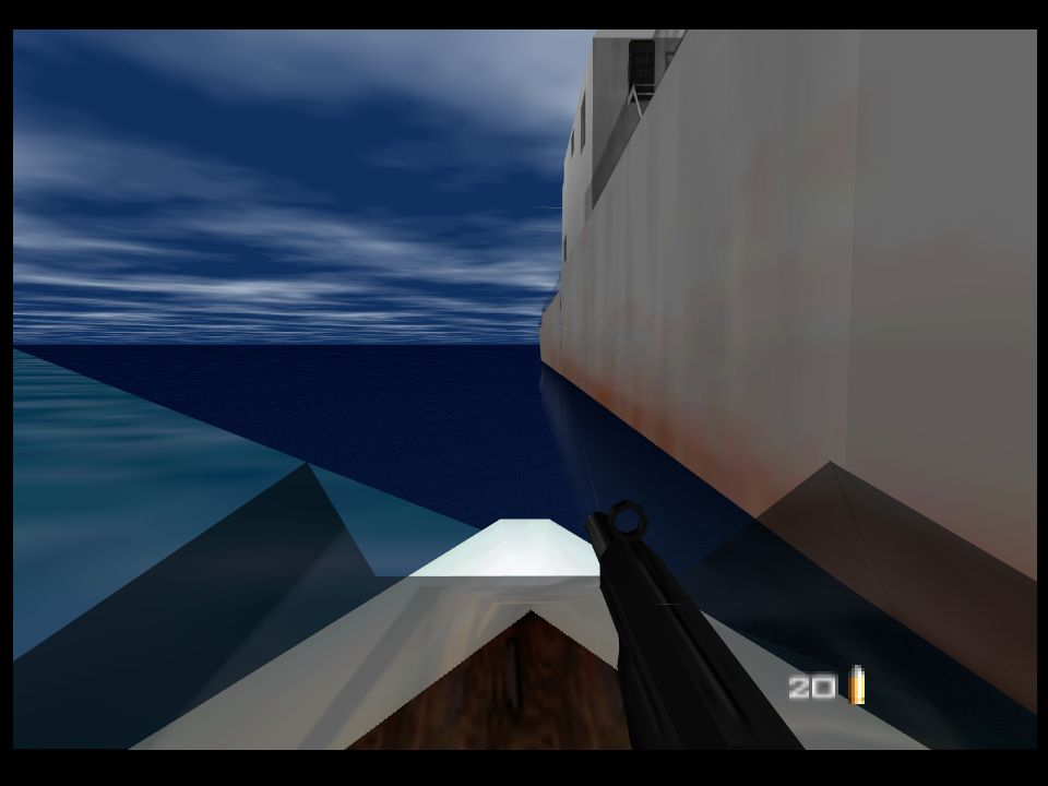
That fix also solved the water texture issue in Golden Eye Frigate level. However I met another issue there: the colors of water and sky were somehow wrong, not as dark as they have to be:
The color combiners for water and sky mix texture color with shading color. Since texturing looks correct, the problem should be in the shading color. I compared color of vertices calculated by GLideN64 with color calculated by AL RDP at the same points. The results were very close. I decided to hack the color combiner for water: remove texturing and draw only the shading color:
This result puzzled me at first. The input data is nearly the same but the output is dramatically different. Color of top vertices is dark and rather blue, so the result should be as on the right screen shot from AL RDP. Then I noticed that value of W is very high for top vertices but is very low at the bottom:

This explains the problem. N64 hardware is not powerful enough to perform perspective correction for colors. It uses plain Gouraud shading, that is simple interpolation of vertex color. GLideN64 powered by OpenGL. Modern OpenGL applies perspective correction to all outputs of vertex shader by default, including shading color of course. Perspective correction makes shading color almost constant in that case, because the differences in vertex color intensity compensated by differences in vertex W. Luckily, OpenGL allows to disable perspective correction for any parameter. I disabled perspective correction for shading color and finally got the correct result:
Thus, the LLE-specific issues in KI, GE and PD have been fixed. GLideN64 LLE rendering still has unsolved issues mentioned in the previous article. This work has WIP status. Alpha builds available to project's patrons on Patreon.com.


Sunday, November 3, 2019

Rendering in Low Level Emulation mode. Part II

Hi!

In the previous article I described how N64 hardware does polygons rasterization and how graphics plugins convert low-level rasterization data into vertices for PC hardware. I also mentioned the problems of the current approach. So, the task is to solve the problems.

When I finally understood how current code for low-level triangles works (yes, I had borrowed it years ago without understanding of its work), I had no good idea why its results are so poor. Everything looked quite reasonable.

When I have problems with understanding how the RDP works, I consult with sources of angrylion's software graphics plugin aka AL RDP. This plugin is very precise emulator of RDP, a digital model of the actual chip. The sources can give you information about RDP work, which you will not find in documentations. Extraction of information this way is not easy but often it is the shortest way. I found how edge walking implemented here and compared it with GLideN64 code. No surprises here - AL RDP code is more complex and precise, it does many more checks and manipulations with input data and output result. So I decided to adapt that code for my needs in hope that it will bring better results. I spend a week or two on experiments but got as bad or even worse results as before. Most likely I did mistakes somewhere. Anyway, my disappointments in results turned into disappointments in the approach itself.

At some moment I got an idea: why should we walk the same way as actual hardware does? We have three edges, we need to find where they are intersecting. This is simpler to do with just solving lines equations! Actually, this idea came to olivieryuyu first. He started to learn that matter earlier and provided me with articles and documents how things work and how low-level data can be used to extract vertices. I did not pay attention on it first, trying to improve the old method, which already works somehow.

So, let's see how can we get vertices without edge walking. We need the line equation for each edge. Equation of a line looks as this:
y = mx + y0
where m is the slope and y0 is the y coordinate of its intersection with the y-axis.
Open our diagram for low-level triangles again:
We have inverse slope for each edge, so the equation of a line in our case is
x = ky + x0
where k is edge's inverse slope and x0 is the x coordinate of its intersection with the x-axis.
We have intersection point for the major edge H, which is XH. We also have intersection point for the first minor edge M, which is XM. Both intersection points have the same y coordinate, which is coordinate of the previous scan-line. Let's set y-axis to that y coordinate for convenience and denote it as Y0.
Thus, we have two equations:
x = DxHDy * y + XH
x = DxMDy * y + MH
where y = (Y - Y0).
We can easily solve the system of these two equations and get exact coordinates of intersection point of the edges. Good. Let's denote coordinates of that point as (X1,Y1).
How to get parameters values for that point? It is simple: with DpDe. Value of P at (X1,Y1) is
P1 = P + DpDe * (Y1 - Y0)

Next vertex is intersection point of minor edges M and L. As you see on the diagram, y coordinate of mid vertex is in range [YM,YM+1]. XL also does not coincide with vertex x coordinate in general case. L edge intersects XL, but where? "XL is calculated where the L edge intersects the next subpixel at or below the mid vertex." The intersection can be at YL or YL+1. Can we calculate it exactly? It looks as we can. Let's calculate XM` for edge M at YM:
XM' = DxMDy * YM + MH
If XM` is the same as XL then mid vertex coordinates are (XL,YM).
Otherwise, edge L intersects point (XL,YM+1), so we can build line equation for L using this point, and then find intersection point of M and L edges. Let's denote mid vertex coordinates as (X2,Y2).

Now we know coordinates of the second vertex, but the vertex is not on the major edge. How will we get values of all parameters for that vertex? It is not hard either:

  • find the point on the major edge at mid vertex Y, that is Y2. Let's name x coordinate of that point as XH', so the point's coordinates are (XH',Y2).
  • calculate parameters for point (XH',Y2) using DpDe.
  • We know X2 and XH', so we can calculate the distance X2-XH', and thus we can calculate value of every parameter with DpDx:
    P2 = P + DpDe * (Y2 - Y0) + DpDx * (X2 - XH')

Since we have line equations for all three edges, we can find intersection point of the major edge H and minor edge L, which is the third vertex of our triangle. This vertex lies on edge H, so its parameters calculated the same way as for the first vertex. Thus, we've got three vertices per low-level triangle. The task completed.

The algorithm looks simple, does not it? I made first-shot implementation pretty quickly, but then I spent weeks trying to make it work at least not worse than the older method, and some more time to make it better. The devil in the details.

Which problems of the old method are solved with the new one:

  • Performance. New method produces 3 vertices and thus 1 hardware triangle per low-level triangle. When low-level triangle represents trapezoid, it still requires 4 vertices and thus two hardware triangles, but it is a rare case. Thus, the new method produces significantly less data for PC hardware than the old one. I would be happy to say that it led to significant boost in performance, but it is not true. The difference in performance is almost negligible. The bottle-neck of LLE rendering is not in amount of data and number of polygons, it is in number of API calls. Each LLE triangle rendered with separate GL draw call, while in HLE mode the plugin caches triangles when possible. I had no idea how to implement triangles caching for LLE mode, and, truly speaking, did not care much about it. This time I looked at the problem more carefully and found a simple but efficient way to cache LLE triangles. The speed-up after that optimization can be called tremendous. Now GLideN64 is even faster than Z64, which is also well optimized.
  • Lines support. As I explained before, line is a special case of low-level triangle, and it requires a special support in the code. It was not done for the old method, so lines rendered incorrectly. I've implemented support for special cases for the new method:

    It is still not perfect if compare with HLE mode lines, and I hope to improve it.
  • Sticking out polygons. I see them no more:
  • Depth compare issues. Some poke-through issues have been fixed:
  • Issues with shading disappeared:
  • Depth buffer emulation issues. I adapted my software depth render to work with new LLE triangles. Depth buffer based effects such as coronas now work correct, as you may see on the previous screen shot.
Unsolved problems:
  • Poke-through issue with decal surfaces. Decal textures worked poorly with old method and still work the same with the new one:

    I still don't know where the problem hides.
  • Gaps between polygons. No positive changes here. I just hope that the new method brings no regressions in compare with the old one.
And the most interesting from the practical view question: does the new method help to fix issues with Golden Eye and Killer Instinct Gold? No, it does not.

To be continued.


Saturday, October 26, 2019

Rendering in Low Level Emulation mode. Part I.

 Hi!

I'm currently working on improving Low Level Emulation (LLE) support in the plugin. It is hard and interesting topic, full of challenges. I decided to write several technical articles to describe the issues encountered and their possible solutions.

I have already written about differences between High Level Emulation (HLE) and LLE, and about problems which each of the approaches can and cannot solve. You may read this introduction article: https://gliden64.blogspot.com/2014/11/a-word-for-hle.html and this one https://gliden64.blogspot.com/2014/11/lle-is-here.html.

Three years ago, we started to decode remaining microcodes. We successfully completed this task and now GLideN64 can run any N64 game in HLE mode. It is a great result. So, why bother with LLE? Apart from the fact that it is a challenging task and we like challenges, there are practical reasons:
  • there are few games, such as Golden Eye and Killer Instinct, which directly use low-level RDP triangles from HLE display lists. RDP stands for Reality Display Processor, N64 polygons rasterization unit. That is, some LLE support is required for complete emulation even in HLE mode.
  • HLE emulation is not guaranteed to be perfect. LLE rendering helps to separate HLE specific errors from RDP ones.
Current implementation of LLE rendering was taken from Z64 - a LLE graphics plugin by ziggy (Vincent Penne). Z64 project started in 2007 and currently discontinued. It is still the best LLE graphics plugin with hardware rendering. It has plenty of issues related to polygons rendering, and GLideN64 inherited them all.

So, let's see why rendering of low-level triangles with PC graphics API is so problematic. First, let's see what low-level triangles are. RDP has 8 triangle commands:
  1. Non-ShadedTriangle
  2. Shade Triangle
  3. Texture Triangle
  4. Shade, Texture Triangle
  5. Non-Shaded, ZBuff Triangle
  6. Shade, ZBuff Triangle
  7. Texture, ZBuff Triangle
  8. Shade, Texture, ZBuff Triangle
The difference between these commands is in the amount of data provided. The first command, Non-ShadedTriangle, is the simplest. It has only constant color. The last one, Shade Texture ZBuff Triangle, is the most complex and general case with shade (that is per-vertex) color, texturing and z buffering. So, in the simplest case render just fills triangle area with a color. Shade commands perform Gouraud shading.  Texture commands do texturing with (optional) perspective correction. ZBuff commands perform z compare. The common part for all these commands is the data, which defines triangle's position on screen. This data described in "Nintendo Ultra64 RDP Command Summary" document by Silicon Graphics Computer Systems, Inc. You can find this document in Internet. Let's see (click for full-size picture):


What is strange on this diagram? There are no vertices coordinates. We have inverse slope for major edge and two minor edges. We also have six coordinates XH, YH, XM, YM, XL, YL, none of which correspond to actual triangle's vertex in general case. Actually, it is not strange if we recall that RDP is just a resterizer. Vertices are high-level data. Vertices processed by Reality Signal Processor (RSP). RSP performs vertices transformation, lighting, culling and clipping. RDP restirizes (renders) the data prepared by RSP. RDP resterization process is not unique. It works alike many software single-thread renders. You may find pretty good explanation of that process in this article.

Let's check the diagram again. Each square is a pixel that is a dot on the screen. In order to render polygons with sub-pixel precision, X coordinates are represented by fixed point numbers in format s15.16, meaning a signed 32bit value with 16bit fractional part. It is pretty good precision. It is not so for Y, which is in s11.2 format (signed 16bit value with 2bit fractional part). Indeed each row of pixels corresponds to a scan-line, each of them being divided by 4 horizontal sub-areas, and Y coordinates only correspond somehow to a scan-line sub-area. So, Y precision is not that good as X one.

Here how N64 rendering works:
  1. Start from the top of the scan-line, which holds YH. In the examples above it is YH-2. We have intersection point of major edge with the scan-line: (XH, YH-2). Intersection point of the first minor edge with this scan-line is (XM, YH-2)
  2. Descend down by the edges using given edges inverse slopes. For example, for YH-1, X coordinate for point on major edge is XH`= XH + DxHDy; X coordinate for point on minor edge is XM`= XM + DxMDy. For YH it will be XH`= XH + DxHDy*2, XM`= XM + DxMDy*2  and so on.
  3. Render nothing until XH`-XM` is positive for Left Major Triangle case, or until XH`-XM` is negative in case of Right Major Triangle. These conditions mean that our edge points are not inside the triangle yet. As you may see in the examples above, rendering is not started yet at YH.
  4. Rendering starts, meaning pixel rasterization between calculated edge points. Continue until YM coordinate. At this point we start to slide along the second minor edge. XL is used as the starting point on the minor edge and DxLDy as inverse slope. Continue rasterization process as long as edge points are inside the triangle. As you may see on the diagram, rasterization should continue until YL.
Edge walking process looks like this:


Of course, render can't lit pixels partially. The color of a pixel partially intersecting with the polygon depends on the amount of pixel's area covered by the polygon and the current coverage mode. I made this picture to illustrate how low-level triangle data is used to define the area covered by the triangle. It will help me to explain how this data is used to extract vertices information for hardware rendering. But first let's see how pixels inside the triangle are colored. The picture above demonstrates the simplest case, when the triangle is filled with some constant color. How more complex cases work? 

As I mentioned before, the amount of data provided for the triangle being rendered depends on triangle command. It can be shading color, texture coordinates, Z coordinate (depth) and W coordinate for perspective correction. All these kinds of data are given not per-vertex, since we have no vertices. Instead, all the information is given for the major edge. Initial values are calculated for point where the major edge H intersects the previous scan line, (XH, YH-2) in our examples. Besides the initial value, each parameter P provided with DpDe and DpDx values. DpDe is used to calculate change of that parameter along the edge. So, value of every parameter on the major edge can be calculated for each sub scan-line. DpDx is used to calculate the change of the parameter along the scan-line. Thus, it is enough to have an initial value of parameter P with DpDe and DpDx to calculate P for each pixel inside the triangle.

Now let's see how N64 low-level triangle data is used to extract information for PC hardware triangle vertices. I'll describe the method, which is used by Z64, Glide64 and GLideN64. May be there are other approaches, but I know only this one. If you will look at the source code it may appear tangled and complicated for you. Actually, the idea is simple. The algorithm uses the same edge-walking mechanism described above, with some short-cuts for optimization purposes:
  1. Start from the top of the scanline
  2. Descend down by the edges using given edges inverse slopes until distance between points on edges is positive for Left Major Triangle case, or is negative in case of Right Major Triangle.
  3. Take point on the major edge as the first vertex. Calculate color, depth and texture coordinates for that point using DpDe.
  4. If distance between points on major and minor edges is not zero, take point on the minor edge as the second vertex. Calculate color, depth and texture coordinates for that point using DpDx.
  5. Move down until YM coordinate. Repeat steps 3-4. 
  6. Move down until YL coordinate. Repeat steps 3-4.
This algorithm has some flaws:

  • Performance. In general case the algorithm produces 6 vertices per low-level triangle and thus requires 4 hardware triangles to render it. For instance, the picture below illustrates a real case. What you see as one triangle actually consists of 4 triangles, two of which are so narrow that they look as lines:
    In the best case, when the points of intersection of the major edge with minor ones lie on some sub scan-lines, this algorithm produces only two polygons - top and bottom. That is we have at least two hardware triangles per low-level triangle. It obviously is not very good, but performance it is not the main problem of that method.
  • Lines are not supported:
    Line, as well as trapezoid in general case, can be drawn by one low-level triangle command. To do that, inverse slopes of major and minor edges must be the same. In this case the edges will be parallel and form a line with a width equal to distance between XH and XM. It is a special case, which requires special support in the algorithm. It was not done.
  • Sticking out polygons:
    This problem can be related to the previous one. It seems that the problem appears for very narrow polygons in a model.
  • Depth compare issues:
  • Depth buffer emulation issues. I failed to apply my software depth render to LLE triangles, so the only way to get depth buffer content in RDRAM is to copy it from video memory, which can be slow.
  • Shading issues:
  • Gaps between polygons. It is one of very hard problems, which hardware graphics plugins still can't solve. This problem presents in HLE, but in LLE it is worse:
  • And particularly annoying issues are related to Golden Eye and Killer Instinct Gold, which need LLE triangle support even in HLE mode:


Wednesday, April 3, 2019

Hotfix

Hello,

Some last minutes modifications broke Dark Rift, and that bug sneaked into the 4.0 release.
It is fixed now. Please download updated binaries from GLideN64 GitHub Releases. Sorry for inconvenience.

Monday, April 1, 2019

Public Release 4.0

Hello,

Today is time to set new Release tag to master branch.
Previous Release 3.0 was a revolutionary one because of massive changes in plugin's architecture and new possibilities opened by these changes. This release is rather evolutionary. It continues tendencies started in the previous version. Of course, new features had been developed too. Lets see:

Solution for HLE problems

The main theme of the new release is solution of HLE-related problems. It started with long long awaited HLE implementation of BOSS ZSort microcode made by Gilles Siberlin.

Then olivieryuyu and me completed our "Mission Impossible 2" : HLE implementation of microcodes for "Indiana Jones" and "Battle for Naboo".That was a huge and incredibly hard work. Successful completion of that task ultimately closed "HLE not supported" issue. All N64 games now can be run in HLE mode. olivieryuyu wrote an article about this microcode: "The masterpiece graphic microcode behind the Nintendo 64 version of Indiana Jones and the Infernal Machine and Star Wars Episode I: Battle for Naboo". I highly recommend to read it.

Next step was to fix issues caused by incomplete or incorrect implementation of some HLE commands, which caused HLE-only glitches. We started with re-implementation of S2DEX microcode, which is designed to draw such 2D objects as sprites and backgrounds. olivieryuyu decoded that huge and tangled microcode and we made new HLE implementation of it, trying to reproduce original algorithms as close as possible. That work took us circa six month.

We also fixed several small HLE issues, where glitch was caused by an issue in some command. Such fixes also required microcode analysis. Thanks to olivieryuyu's efforts we fixed:

Regressions fixes.

The second big topic of this new release is fixing of regressions.

Unfortunately, each big release is brings not only new features and fixes, but also new bugs. Complete testing is very hard and tedious process. Fortunately, users are founding and reporting us about issues. One of my goals for this release was to fix all known regressions. I combed project's bug tracker for such bugs. To my surprise, many reported issues were actually old and very old regressions. I even found regressions, which were made before the very first public release. I fixed all these issues and I hope that this release will not bring many new ones.

New features.

1. As you know, GLideN64 has special mode for precise emulation of N64 depth compare. This mode helps to fix many minor and some major issues with depth compare, but it has some limitations:
  • serious performance drop in some games
  • incompatibility with Multi-Sample Anti Aliasing (MSAA)
Logan McNaughton aka loganmc10 found OpenGL extensions, which helped us to weaken the performance issue greatly. Now you can use N64 depth compare freely if your hardware supports required extensions. This mode is still incompatible with MSAA, but now we have a solution. I implemented Fast Approximate Anti Aliasing (FXAA) , which you can enable along with N64 depth compare.

2. Ultimate solution for "remove these darn annoying black boarders" issue: Overscan feature. Now you may crop output image as much as you want.

3. User profiles. You may create profiles with different settings and switch between them. For example, you may create a profile with 2D fixes enabled to play 2D games, or create a profile with N64 depth compare + FXAA enabled.

New supported games

I already mentioned implementation of new microcodes, which finally made it possible to run any game with HLE. However, there are still games, which can't run properly because they do something weird what GLideN64 does not expect and can't emulate yet. Example of such game is Super Bowling 64. The way that game programmed makes it hard to emulate on PC hardware. Finally I found a way how it can be done. That fix then helped me to solve split screen issue in NASCAR 2000. Another example of hard to emulate issue is multiplayer mode in GoldenEye 007 and Perfect Dark with 3 or 4 players. It was fixed too.

Other

It is impossible to list all solved issues. We closed more than 175 issues during this release cycle .
You may read my change-logs on Patreon for details.

Acknowledgements:
  • Thanks to all backers of "Indiana Jones and the Infernal Machine" crowdfunding campaign on Indiegogo. We hardly would take that task without your support.
  • Thanks to all my patrons on www.patreon.com/Gliden64 I very appreciate your support.
  • Thanks to all users of https://github.com/gonetz/GLideN64. Your bug reports and feedback greatly help us to improve quality of the program.
Very special thanks to olivieryuyu, the author of incredible microcode decoding works.

Downloads:

To help the project:

Friday, March 1, 2019

Fixes in S2DEX microcode.

Hello,

S2DEX microcode was developed to simplify development of 2D games. It provides macro commands to create sprites and backgrounds. S2DEX2 modification of S2DEX can self-load with F3DEX2 microcode and thus can be used to create 2D sprites and backgrounds in 3D games. Many N64 games use S2DEX, so all modern HLE graphics plugins implement it.

S2DEX implementation in GLideN64 was too high level. Actual microcode commands are very complex. The microcode is documented, but the documentation does not cover some tiny details in internal mechanics. Thus, S2DEX implementation not always worked right. olivieryuyu decided to not rely on documentation and decode the microcode itself. The goal of that new decoding project was to implement commands in HLE as close as possible to LLE and obtain the result, which is as good as with LLE or better.

It was very long and hard project, which took circa six months. We started form relatively simple sprite commands: OBJ_RECTANGLE, OBJ_RECTANGLE_R and OBJ_SPRITE. We fixed calculation of screen and texture coordinates of sprites. There are several revisions of the microcode, and each revision does the calculations in slightly different way. The fix eliminated several minor glitches and a major one, in Parlor! Pro 64:


Then we started decoding and implementation of remaining commands: BG_1CYC and BG_COPY, which are used to draw large 2D objects such as backgrounds. It was very hard task. These functions are very large and tangled. After several months of hard work both background commands were implemented and now they produce exactly the same result as in LLE mode on all games we tested.
One of results of our work - correct background in Neon Genesis Evangelion:

From one side, it is great result because the commands are very large and complicated. From the other side, LLE by itself not always gives perfect result. You may run previous releases of the plugin in LLE mode and find numerous graphics glitches in 2D games. Some of glitches caused by errors in texture loading code. Backgrounds commands do texture loading in quite weird manner, which "normal" game code never uses. I fixed several hard issues in plugin's texturing subsystem during development of that project. However, many glitches remained after these fixes. These glitches can be called "the curse of hardware rendering". There are two main groups of such glitches:

  • gaps between polygons. Background commands can not draw background by one piece because of limited texture memory. Background image becomes split on narrow strips. Each strip is loaded in texture memory and rendered by separate rectangle. There are no gaps between rectangles, but gaps between images in them may appear when rendering resolution is higher than game's native resolution. It usually happens when size of the image is not exactly the same as size of area where it will be rendered. Texture scaling in higher resolution may cause fetching texels out of texture image bounds, thus cause artifacts, which look as gaps between polygons.
  • garbage between polygons. Looks like a line of colored garbage between two polygons. Is is seldom kind of glitches, but it does not fixed by switching to native resolution. I did not find yet, how it can be cured.

So, new implementation has issues, but most of them appears only in non-native resolutions. GLideN64 already has tool to eliminate issues with 2D graphics in high resolutions. You may enable "Render 2D elements in native resolution" option to activate it. I adopted that tool to work with new background commands. Result is quite good in general. For example, StarCraft backgrounds have glitches in high-res, but "Render 2D elements in native resolution" eliminates them:
However, the tool is not bug-free by itself and sometimes it is slow. Taking all these issues into account we decided to keep old implementation of background commands and make an option to switch between old "one-piece background" implementation and new "stripped background" one. We recommend to use the new implementation as default one.

Tuesday, February 26, 2019

Fast Approximate Anti-Aliasing aka FXAA

According to multiple user requests, GLideN64 now supports Fast Approximate Anti-Aliasing aka FXAA. FXAA is post-processing filter, which eliminates aliasing. Check the image to see how it works with Super Mario 64 (click for full-size image).


 As you may notice, traditional Multisample anti-aliasing aka MSAA gives the best result. Result of FXAA is decent, but not as good. So, why use it? As you may know, N64 depth compare is hard to emulate properly on PC hardware. I made shader based emulation of N64 depth compare. Currently it can be enabled without sacrifice in performance, but it is not compatible with MSAA. That is if you enabled N64 depth compare you lost anti-aliasing. Now you may enable FXAA and N64 depth compare and play without major sacrifice in graphics quality. Also, FXAA is less demanding to hardware power than MSAA. Anti-aliasing techniques as FXAA are the only way to get AA  on mobile devices with GL ES 2.0. FXAA is currently available in WIP builds and of course it will be included into upcoming public release.

Monday, February 18, 2019

HLE implementation of BOSS ZSort microcode.

Hello!

One of the most exciting features of the upcoming public release is long awaited
HLE implementation of BOSS ZSort microcode. This microcode is used in two great racing games: World Driver Championship and Stunt Racer. Both games were unsupported by emulators for a long time due to core issues. Several years ago these issues were resolved, and the games became playable with graphics plugins, which support LLE mode. GLideN64 supports LLE mode and it can run the games in LLE, but performance is far from good.

HLE mode is usually much faster and has less glitches. The problem is that BOSS developed custom microcode for these games and no information about this microcode leaked. Thus, it had to be decoded from asm code. This work requires skills and patience. GLideN64 obtained the first results in microcode decoding yet in 2016, when Gilles Siberlin aka Gillou68310 decoded microcode for Kuiki Uhabi Suigo. Then me and olivieryuyu completed several decoding projects. Gilles started to work on decoding of BOSS ZSort microcode at the end of 2017.

This microcode is deep modification of ZSort microcode released by Nintendo in 1999. ZSort intended to solve problem with N64 low fill-rate. While N64 supports Hi-Res graphics, not so many games could use hi resolutions without sacrifices in speed or quality because of bottlenecks in the RDP. ZSort sorts objects by depth value before rendering and draws them in order from far to near thus eliminating the use of depth buffer. It not only saves memory but also frees RDP from rendering the depth buffer, which almost doubles the fill-rate for color buffer.

Unfortunately, ZSort was released too late in the system's life and was used only in the engine for series of soccer games, for example Mia Hamm Soccer 64. ZSort is very specific microcode; it has almost nothing in common with F3D/F3DEX series of microcodes which are used in most of N64 games. I had documentation for it and sources of two demos which use it, but nevertheless I spend weeks to implement and debug it.

It seems that ZSort also had some performance flaws, so when BOSS decided to use it for new games, BOSS programmers re-worked it a lot. The resulted ucode differs from original ZSort so much that it was clear - it must be decoded from asm to be HLEed. So, Gilles Siberlin took that task and successfully completed it. Since I did not participate in this task, I don't know all the details. Cite from Gilles: "Wow this is one hell of an optimized ucode!!! The ucode is doing both audio and graphic processing, plus everything fits in less then 1024 instructions so no overlay needed." It is unique case when ucode processes both audio and graphic, no other ucode does it. So, now GLideN64 has a bit of audio processing code. Emulation of this microcode requires modification of N64 SP_STATUS register. That is not allowed by original zilmar's specs for graphics plugin. mupen64plus implemented necessary changes in core to fix that issue and now both World Driver Championship and Stunt Racer work fine with mupen64plus. Work with Project64 is not guaranteed.