I'm currently working on improving Low Level Emulation (LLE) support in the plugin. It is hard and interesting topic, full of challenges. I decided to write several technical articles to describe the issues encountered and their possible solutions.
I have already written about differences between High Level Emulation (HLE) and LLE, and about problems which each of the approaches can and cannot solve. You may read this introduction article: https://gliden64.blogspot.com/2014/11/a-word-for-hle.html and this one https://gliden64.blogspot.com/2014/11/lle-is-here.html.
Three years ago, we started to decode remaining microcodes. We successfully completed this task and now GLideN64 can run any N64 game in HLE mode. It is a great result. So, why bother with LLE? Apart from the fact that it is a challenging task and we like challenges, there are practical reasons:
- there are few games, such as Golden Eye and Killer Instinct, which directly use low-level RDP triangles from HLE display lists. RDP stands for Reality Display Processor, N64 polygons rasterization unit. That is, some LLE support is required for complete emulation even in HLE mode.
- HLE emulation is not guaranteed to be perfect. LLE rendering helps to separate HLE specific errors from RDP ones.
Current implementation of LLE rendering was taken from Z64 - a LLE graphics plugin by ziggy (Vincent Penne). Z64 project started in 2007 and currently discontinued. It is still the best LLE graphics plugin with hardware rendering. It has plenty of issues related to polygons rendering, and GLideN64 inherited them all.
So, let's see why rendering of low-level triangles with PC graphics API is so problematic. First, let's see what low-level triangles are. RDP has 8 triangle commands:
- Non-ShadedTriangle
- Shade Triangle
- Texture Triangle
- Shade, Texture Triangle
- Non-Shaded, ZBuff Triangle
- Shade, ZBuff Triangle
- Texture, ZBuff Triangle
- Shade, Texture, ZBuff Triangle
The difference between these commands is in the amount of data provided. The first command, Non-ShadedTriangle, is the simplest. It has only constant color. The last one, Shade Texture ZBuff Triangle, is the most complex and general case with shade (that is per-vertex) color, texturing and z buffering. So, in the simplest case render just fills triangle area with a color. Shade commands perform Gouraud shading. Texture commands do texturing with (optional) perspective correction. ZBuff commands perform z compare. The common part for all these commands is the data, which defines triangle's position on screen. This data described in "Nintendo Ultra64 RDP Command Summary" document by Silicon Graphics Computer Systems, Inc. You can find this document in Internet. Let's see (click for full-size picture):

Let's check the diagram again. Each square is a pixel that is a dot on the screen. In order to render polygons with sub-pixel precision, X coordinates are represented by fixed point numbers in format s15.16, meaning a signed 32bit value with 16bit fractional part. It is pretty good precision. It is not so for Y, which is in s11.2 format (signed 16bit value with 2bit fractional part). Indeed each row of pixels corresponds to a scan-line, each of them being divided by 4 horizontal sub-areas, and Y coordinates only correspond somehow to a scan-line sub-area. So, Y precision is not that good as X one.
Here how N64 rendering works:
- Start from the top of the scan-line, which holds YH. In the examples above it is YH-2. We have intersection point of major edge with the scan-line: (XH, YH-2). Intersection point of the first minor edge with this scan-line is (XM, YH-2).
- Descend down by the edges using given edges inverse slopes. For example, for YH-1, X coordinate for point on major edge is XH`= XH + DxHDy; X coordinate for point on minor edge is XM`= XM + DxMDy. For YH it will be XH`= XH + DxHDy*2, XM`= XM + DxMDy*2 and so on.
- Render nothing until XH`-XM` is positive for Left Major Triangle case, or until XH`-XM` is negative in case of Right Major Triangle. These conditions mean that our edge points are not inside the triangle yet. As you may see in the examples above, rendering is not started yet at YH.
- Rendering starts, meaning pixel rasterization between calculated edge points. Continue until YM coordinate. At this point we start to slide along the second minor edge. XL is used as the starting point on the minor edge and DxLDy as inverse slope. Continue rasterization process as long as edge points are inside the triangle. As you may see on the diagram, rasterization should continue until YL.
Edge walking process looks like this:

Of course, render can't lit pixels partially. The color of a pixel partially intersecting with the polygon depends on the amount of pixel's area covered by the polygon and the current coverage mode. I made this picture to illustrate how low-level triangle data is used to define the area covered by the triangle. It will help me to explain how this data is used to extract vertices information for hardware rendering. But first let's see how pixels inside the triangle are colored. The picture above demonstrates the simplest case, when the triangle is filled with some constant color. How more complex cases work?
As I mentioned before, the amount of data provided for the triangle being rendered depends on triangle command. It can be shading color, texture coordinates, Z coordinate (depth) and W coordinate for perspective correction. All these kinds of data are given not per-vertex, since we have no vertices. Instead, all the information is given for the major edge. Initial values are calculated for point where the major edge H intersects the previous scan line, (XH, YH-2) in our examples. Besides the initial value, each parameter P provided with DpDe and DpDx values. DpDe is used to calculate change of that parameter along the edge. So, value of every parameter on the major edge can be calculated for each sub scan-line. DpDx is used to calculate the change of the parameter along the scan-line. Thus, it is enough to have an initial value of parameter P with DpDe and DpDx to calculate P for each pixel inside the triangle.
Now let's see how N64 low-level triangle data is used to extract information for PC hardware triangle vertices. I'll describe the method, which is used by Z64, Glide64 and GLideN64. May be there are other approaches, but I know only this one. If you will look at the source code it may appear tangled and complicated for you. Actually, the idea is simple. The algorithm uses the same edge-walking mechanism described above, with some short-cuts for optimization purposes:
- Start from the top of the scanline
- Descend down by the edges using given edges inverse slopes until distance between points on edges is positive for Left Major Triangle case, or is negative in case of Right Major Triangle.
- Take point on the major edge as the first vertex. Calculate color, depth and texture coordinates for that point using DpDe.
- If distance between points on major and minor edges is not zero, take point on the minor edge as the second vertex. Calculate color, depth and texture coordinates for that point using DpDx.
- Move down until YM coordinate. Repeat steps 3-4.
- Move down until YL coordinate. Repeat steps 3-4.

This
algorithm has some flaws:
- Performance. In general case the algorithm produces 6 vertices per low-level triangle and thus requires 4 hardware triangles to render it. For instance, the picture below illustrates a real case. What you see as one triangle actually consists of 4 triangles, two of which are so narrow that they look as lines:In the best case, when the points of intersection of the major edge with minor ones lie on some sub scan-lines, this algorithm produces only two polygons - top and bottom. That is we have at least two hardware triangles per low-level triangle. It obviously is not very good, but performance it is not the main problem of that method.


- Lines are not supported:Line, as well as trapezoid in general case, can be drawn by one low-level triangle command. To do that, inverse slopes of major and minor edges must be the same. In this case the edges will be parallel and form a line with a width equal to distance between XH and XM. It is a special case, which requires special support in the algorithm. It was not done.

- Sticking out polygons:This problem can be related to the previous one. It seems that the problem appears for very narrow polygons in a model.

- Depth compare issues:

- Depth buffer emulation issues. I failed to apply my software depth render to LLE triangles, so the only way to get depth buffer content in RDRAM is to copy it from video memory, which can be slow.
- Shading issues:

- Gaps between polygons. It is one of very hard problems, which hardware graphics plugins still can't solve. This problem presents in HLE, but in LLE it is worse:

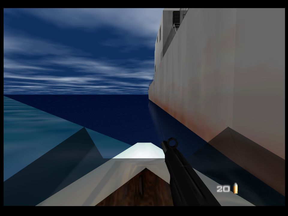
- And particularly annoying issues are related to Golden Eye and Killer Instinct Gold, which need LLE triangle support even in HLE mode:


you should get in touch with a mathematician to come up with a better option
ReplyDeleteI'm a mathematician. Kind of.
DeleteWow... @Gonetz you're pushing the N64 to the highest level. I take my hat off.
ReplyDeleteThanks :)
DeleteHi Gonetz, I started to wrote a CPU RDP LLE plugin long time ago. You didn’t mention it in the flaws but you also have the "odd" filling mode (for interlace effects) which can be tricky to implement with general GPU rasterization process. The RDP use a line counter to determine if line is odd or even.
ReplyDeleteBecause of this, I realized the only uninterrupted "primitive" call is the horizontal line.
If you plan to represent native resolutions (320×240, 384×288, 640×480, 720×576) it shouldn’t be a problem, but I don’t know how unative resolution could be handles.
It was years ago, and I don’t remember all the details. LLE is fascinating, keep the good work!
> (for interlace effects)
DeleteFor interlace effects!!!
Could you give me an example of such effect?
> LLE is fascinating, keep the good work!
Thanks!
Haha, you makes me dig into years old code (and realize my code related to rasterization emulation is lost forever...). So:
DeleteThere is a 64 bits RDP command: Set Scissor (0x2d)
2 bits of this command (25:24) are related to interlace: Video Mode: Enable scissoring of odd/even lines for interlaced displays.
00: Draw all lines
01: Draw odd lines
11: Draw even lines
The other place is maybe something you already knows: The 17 bits VI global register:
1 bit is "Enable Serrate" (interlace)
Last thing is Vertical Current Line Register (0x04400010)
Quote:
This register is updated once per vertical line to reflect the current line being displayed. In interlaced mode, the least significant bit will be constant for the current field. A write to this register does not change the vertical line currently being displayed. Instead, it clears any currently asserted interrupt caused by the VI_V_INTR_REG register.
The reason why those effects are hard to emulate in non native resolution is because odd/even lines does not have save screen size (width of 1/1080 on HD screen VS 1/240 or 1/576 on N64).
Now, I talk mostly of the hardware side. I'm not sure how games are using them but I suggest to keep an eye on those registers to detect a potentatialy "interlace dependent" effect (Perfect dark glasses/lens?).
http://en64.shoutwiki.com/wiki/VI_Registers_Detailed
https://patater.com/gbaguy/day3n64.htm
Hope this help. Keep the good work!
Yes, the plugin processes interlacing in Video Interface emulation part. It does not skip even/odd lines, just takes into account which field is currently active.
DeleteInterlacing effect in Perfect dark glasses/lens is specially programmed, and does not depend on hardware interlacing. Perfect Dark itself uses 320x220 resolution without interlacing.
gonetz, have you considered not drawing triangles at all and simply drawing horizontal spans with GL_LINES? Kind of a mix between software and hardware rendering. But the expensive part is still done in hardware.
ReplyDeleteNo, I haven't considered drawing horizontal spans with lines. It sounds crazy. I guess, that crazy idea can be used if we will want to emulate interlacing.
DeleteInteresting article! However one thing I cannot figure out is what the DpDy values in the triangle commands are used for, could you explain those please?
ReplyDeleteHardware plugin does not use DpDy at all.
DeleteI tried to understand how it is used by reading sources of AL RDP plugin. If I got it correctly, use of DpDy depends on the kind of P.
For textures, DsDy and DtDy are used to get next texel of T0 tile in the second stage of color combiner.
Depth and color DpDy are used for anti-aliasing, to calculate color and depth of pixels partially covered by the primitive being rendered.